Editor’s Note: To learn more about electrical overstress/electro static discharge (EOS/ESD) floors, including installation tips, check out the article from the November 2016 issue of CoatingsPro.
Conductive and static dissipative floorings and coatings are designed to provide protection from electrical charges causing harm to workers or products. These floor systems are often used in manufacturing facilities, labs, and hospitals. The uses are wide, but the specification of them should be carefully selected.
The Tests
When installing a conductive or static control flooring system, a vapor barrier should always be specified on the negative side of the concrete to isolate the near-surface moisture and prevent direct contact with the static control flooring. Mositure content and emissions should be measured in accordance with ASTM F1869: Standard Test Method for Measuring Moisture Vapor Emission Rate of Concrete Subfloor Using Anhydrous Calcium Chloride and ASTM F2170: Standard Test Method for Determining Relative Humidity in Concrete Floor Slabs Using in situ Probes. These will help to determine the level of moisture in the substrate and the amount that is being emitted. Those, in turn, will be used to select and apply the vapor barrier required for each specific application.
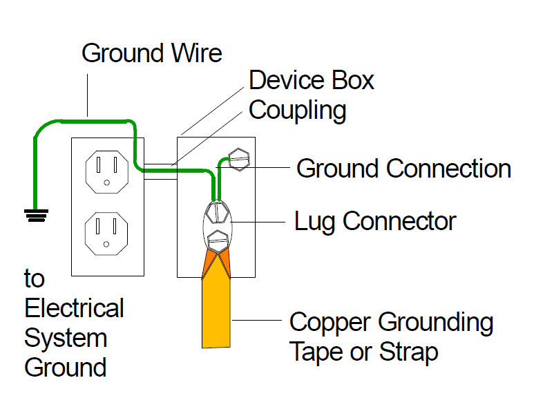
Probably the most misunderstood requirement when applying conductive or electrostatic dissipative floorings or coatings are the grounding and strapping requirements (see Figure 1). According to the Electrostatic Discharge Association (ESDA), the leading authority regarding technical requirements related to static control, all conductive and electrostatic dissipative floors should be grounded.
In the Electrostatic Discharge Association’s technical report TR7.0-01-11, there are three options to provide a ground interface:
1. A ground point built into the ground system specifically for the flooring interface (See Figure 2).
2. A grounded metal column in the building structure.
3. The ground wire in the electrical system.

The decision on which method is used and where grounding points are to be placed should be made by an electrical engineer, and the connection from the strap interface should be done by a professional electrician. The flooring contractor’s responsibility is to properly provide an interface between the flooring or coating and the grounding strap. This is accomplished by placing a copper grounding strap 9 inches (22.9 cm) onto the floor and embedding the strap into the conductive layers of the flooring system. The strap is then connected to the ground point.
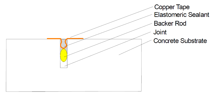
Strapping across joints in the concrete substrate is also required to ensure proper conductivity in the event that the flooring or coating loses intimate contact across the joint (see Figure 3). Straps are usually placed every 6 lineal feet (1.8 m) for electrostatic dissipative floors and every 4 lineal feet (1.2 m) for conductive floors.

Once the installation is complete and the coating system is completely cured, performance tests are required to verify the conductive properties of the finished floor.
There are numerous standards for the testing of conductive properties. The most common are:
• Electrical resistance (in ohms or volts)
• Resistance measurement in combination with a person
• Voltage measurement in combination with a person
Electrical resistance is the most common to test the conductivity of the floor quantitatively. This test can be conducted to verify electrical continuity across the surface (point to point) or from surface to ground (point to ground). The industry standards for testing the electrical resistance of floors are:
• American National Standards Institute (ANSI)/ESDA S7.1
• National Fire Protection Association (NFPA) 99 Health Care Facilities Code
• ASTM F150: Standard Test Method for Electrical Resistance of Conductive and Static Dissipative Resilient Flooring
• International Electrotechnical Commission (IEC) 61340-4-1 Standard test methods for specific applications – Electrical resistance of floor coverings and installed floors
Whichever test method is selected, the testing should be accomplished in strict compliance with the specification. All test methods include specific atmospheric conditions, cleaning of the floor surface and electrodes prior to testing, and calibration of the testing apparatus. With the project closeout documents, the specification should require an official test report in a precise format to certify the electrical conductivity of the flooring system.
Once the floor is in service, the user should test the conductivity periodically to ensure the performance of the floor continues to be appropriate for the service condition.
Knowledge Is Power
When properly installed and tested, conductive and static dissipative floorings and coatings can be effective solutions in many industries. It’s important for everyone from the specifier to the installer to be knowledgeable about the system to make it work correctly.
About the Author:
Steven Schroeder, vice president for the Dex-O-Tex division of Crossfield Products Corp., began in the industry as an installer in 1978. He is an active member of the Construction Specifications Institute (CSI), and he is a past board member of the L.A. chapter of CSI and the Polymer Coatings and Surfacings Institute. For more information, contact: Dex-O-Tex, www.dex-o-tex.com